Earthing test report: free earth resistance test template (Excel and PDF)
Deskely Completions team Singapore
An earthing test report records the resistance of each earth electrode and the continuity of the bonding between equipment and the earthing system. It proves that fault current has a low-resistance path to earth before the installation is energised.
This page gives you a free earthing test report in Excel and PDF for the fall of potential method, and explains how the test works.
- The fall of potential (three-point) method is the most common electrode test.
- Take readings with the potential spike at 52, 62 and 72 % of the distance to the current spike.
- If the three readings agree, the 62 % reading is the electrode resistance.
- Record soil conditions: dry ground reads higher than wet.
How the fall of potential test works
- 01Disconnect the electrode
Isolate the electrode under test from the rest of the earthing system where possible, so you measure it alone.
- 02Place the current spike
Drive the current spike (C) well away from the electrode, typically several times the electrode's length or the size of the grid.
- 03Place the potential spike
Drive the potential spike (P) in a straight line between them, at 62 % of the distance to C.
- 04Take three readings
Read at 52 %, 62 % and 72 % of the distance. If they are close, the 62 % reading stands; if not, move C further away and repeat.
- 05Record and compare
Compare the result with the maximum in your specification, and note the soil conditions.
IEEE 81 and BS 7430 describe the method and its variations for large earthing grids.
The template
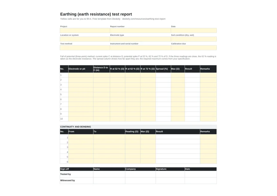
Enter the three readings and the required maximum per electrode; the sheet works out the spread between them and marks the 62 % reading Pass or Fail. The second table records continuity and bonding between equipment and the earth bars.
Where it fits
Earthing tests are part of the electrical pre-commissioning checks, with the electrical inspection checklist and insulation resistance tests. In Deskely, the readings are recorded against the tag and checked against the limit as they are entered.
The Deskely products for this
Frequently asked questions
What is an earthing test report?
A record of earth electrode resistance and bonding continuity measurements, with the method, instrument, conditions and results against the required values.
What is the 62 % rule?
In the fall of potential method, placing the potential spike at 62 % of the distance to the current spike gives the true electrode resistance in uniform soil.
What earth resistance is acceptable?
It depends on the installation and the specification. Substations and sensitive installations need much lower values than a single building electrode.
Why record soil conditions?
Because soil resistivity changes with moisture and temperature, so the same electrode reads higher in dry or frozen ground.
- In production since 2014
- Thousands of daily users
- On MODEC FPSO projects since 2016