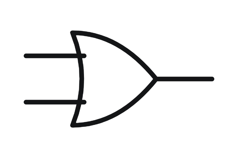
 ANSI / IEEE
 IEC 60617
What the OR gate symbol means
The output is 1 when at least one input is 1.
ANSI and IEC symbols
Where you see it
Digital electronics, PLC function block diagrams, interlock and safety logic, and cause and effect logic.
Related symbols
Frequently asked questions
What does the OR gate symbol look like?
On ANSI drawings: A curved shield shape with a pointed output. In IEC 60617: A rectangle marked ≥1.
Is the OR gate symbol the same in IEC and ANSI?
No. A rectangle marked ≥1.
Where is a OR gate used?
Digital electronics, PLC function block diagrams, interlock and safety logic, and cause and effect logic.
Every electrical tag on your drawings, tested before energisation.Deskely holds the inspection and test records and punch items for every electrical and instrument tag on your project, checked against the register as they are signed.
- In production since 2014
- Thousands of daily users
- On MODEC FPSO projects since 2016