Mechanical link symbol
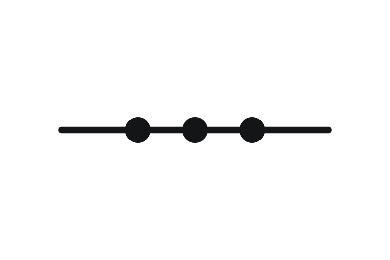
A mechanical link is a physical connection between devices, such as a float arm or linkage.

What the mechanical link symbol means
A mechanical link is a physical connection between devices, such as a float arm or linkage.
How it is drawn
A thin line with small solid dots at intervals.
The mechanical link symbol in each standard
Drawn as ISA 5.1 defines it, as on most US and international legends.
Signal lines are not part of ISO 10628-2. They come from IEC 62424 or ISA 5.1.
German (DIN): Mechanische Verbindung. See DIN P&ID symbols.
Where you see it on a P&ID
On float-operated valves and linked dampers.
Tag codes
The mechanical link is commonly tagged:
- ISA 5.1
Tag formats follow the project numbering procedure. For instruments, the letters follow ISA 5.1, explained on the instrument symbols page.
Related symbols
Frequently asked questions
What does the mechanical link symbol look like on a P&ID?
A thin line with small solid dots at intervals.
What is a mechanical link used for?
A mechanical link is a physical connection between devices, such as a float arm or linkage. You will find it on float-operated valves and linked dampers.
What tag does a mechanical link have?
It is commonly tagged ISA 5.1. The exact tag format comes from the project numbering procedure and the legend sheets.
Is the mechanical link symbol the same in ISA and ISO?
Signal lines are not part of ISO 10628-2. They come from IEC 62424 or ISA 5.1. Companies vary the details, so always check the legend sheets at the front of the P&ID set.
What is the mechanical link called in German?
Mechanische Verbindung. On a German R&I-Fließschema it is drawn to DIN EN ISO 10628-2.
- In production since 2014
- Thousands of daily users
- On MODEC FPSO projects since 2016